
O-rings are doughnut-shaped fluid sealing elements used in machines. These are typically made from an elastomer, but other materials such as thermoplastics and even metals and composites of various materials are used especially for high-temperature environments. The seal is formed when the O-ring is compressed or squeezed between two adjacent surfaces of the joint. The O-ring is housed in a groove also known as the gland.
O-Ring Seal Failure mode(s):
There are three primary O-ring seal failure modes:
- Leakage: The primary function of an O-ring seal is to prevent fluid leakage under operating conditions. Leakage is caused when the fluid pressure is greater than the contact pressure around the O-ring. So as long as the fluid pressure remains below contact pressure, there is no leakage failure.
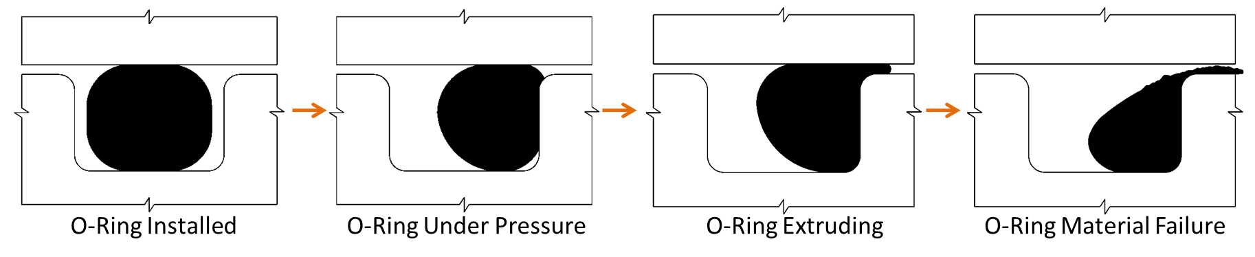
- O-ring extrusion: In general as the fluid pressure goes up, the O-ring is further squeezed into the groove, which helps to seal better. However, this might lead to the extrusion of the O-ring material into the piston-cylinder gap (see image below). Extrusion can be prevented by using backup rings.
- O-ring material failure: As the fluid pressure continues to rise, the O-ring material might undergo an irreversible compression failure. This means that when the fluid pressure is removed, the original contact pressure is lost due to permanent material deformation. This occurs when the maximum O-ring compressive stress exceeds limiting stress. This failure may happen in combination with the extrusion failure.
These are the primary failure modes that can be studied using finite element model-based simulations provided a good material model is available for the O-ring. To obtain a good material model, multiple tests of the O-ring material might be needed including biaxial and shear tests. Additionally, fatigue and cyclic loading failure modes can also be studied using FEA provided experimental data is available. The simulation is then used to extract stress range and mean working stress which is then related to the experimental data to predict fatigue failure. In actual application, it might be best to just replace the O-rings during the regular maintenance schedules.
O-Ring Seal Design
For O-ring design, it is best to follow the manufacturer’s guidelines and select the most appropriate O-ring and corresponding groove size. They already have tables of standard seal sizes and related gland dimensions for specific O-ring types and maximum working pressure. They also provide all the machining tolerances for the piston, cylinder gland dimensions. It is best to use extremes of these tolerances when creating a CAD model for FE simulations as follows:
- Use upper or lower bounds on dimensional tolerances on piston, cylinder, and gland to ensure minimum seal squeeze. This worst-case scenario is designed to investigate potential leakage failure under maximum pressure and temperature loads.
- Use upper or lower bounds on dimensional tolerances on piston, cylinder, and gland to ensure maximum seal squeeze. This worst-case scenario is designed to investigate potential O-ring material compression failure under maximum pressure and temperature load.
Tips to carry out O-Ring seal Simulations in ANSYS:
- In the CAD model, assemble the O-ring in the middle of the gland in the upstretched state. See the cross-section view of the CAD model below. When the FE frictional contact is established, it will ensure proper stretch of the O-ring.
- Use hyperelastic (elastomer) material models such as Mooney-Rivlin, Neo-Hookean, or Ogden depending on O-ring material type. For the simulation example presented in this blog, I’ve used the Neo-Hookean model.
- Use a 2D axisymmetric model unless face seals are involved. Face seals involve bolted joints and will be a topic of another blog.
- For setting up contacts, turn off the trim contact option and ensure that the interface treatment option is set to “Add offset, ramped effects”. Additionally, select asymmetric behavior and ensure that the O-ring is the contact side. Use frictional contacts and use the manufacturer’s recommended frictional factors.
- In case of convergence difficulties, in particular, in the initial load steps, reduce the normal stiffness parameter from 1 to 0.02 or 0.01 if needed.
- Use APDL commands to implement fluid pressure penetration on O-ring contact surfaces.
O-Ring Simulation Example
For the simulation example, a 3D piston-cylinder model was created. A 2D-axis symmetric model was then extracted from the cross-section shown below.
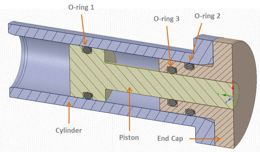
Details of the CAD Model. This is a piston-cylinder assembly with an end cap. Here O-ring#1 and 3 are dynamic whereas #2 is a static o-ring for sealing the end cap.
Simulation Load Steps
The following simulation is done in 9 load steps. Also, check out the video below. The load steps can be seen as “Time” in the video. Here are the details:
- Load step 1: O-rings establish contact with the gland surfaces.
- Load step 2: Cylinder is assembled over the piston. This squeezes the O-rings in the groove.
- Load step 3: Piston is displaced slightly back to ensure the correct positioning of the O-rings within the gland before pressure load is applied.
- Load step 4: Pressure and or temperature loads are applied while the piston is static. Notice the O-rings getting squeezed due to applied pressure.
- Load step 5-9: Piston is displaced back and forth simulating the actual working of the device under pressure and or temperature loads. The fluid pressure prevents the dynamic O-rings from sliding in the gland as the piston moves.
Simulation Results:
This simulation is used to check for the three failure modes described above. The result charts and explanation are presented below:
- The seal contact pressure vs fluid pressure chart clearly shows that the maximum operating fluid pressure of 1500 psi is less than the contact pressure for all O-rings. So leakage will not be an issue. Notice, the static O-ring seal # 2 has larger contact pressure compared to the two dynamic seals due to a larger squeeze in static O-rings.
- The second chart shows O-ring contact pressure vs limiting failure stress of seal material.
- Finally, all three O-rings undergo normal compression deformation under load. There is no sign of any extrusion into the piston-cylinder gap.
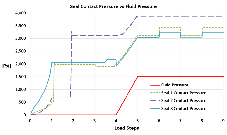
Chart showing the applied fluid pressures and contact pressures of the three O-rings. The contact pressures are significantly higher than the fluid pressure which indicates a safe operation. Notice, that static seal #2 shows higher contact pressure due to the greater squeeze of the static O-ring ~ 16% – 25%. The dynamic O-ring is typically squeezed around 9%-16%.
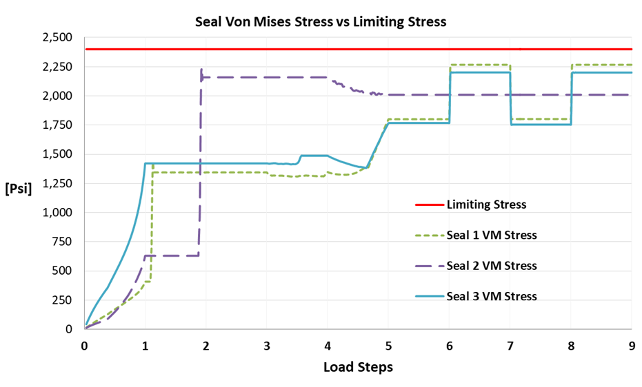
Chart showing the maximum von mises stress in the seal material compared to the limiting stress indicated by the horizontal red line. The maximum VM stress in all O-rings remains below the limiting compressive stress which indicates a safe operation. In other words, the seals will regain their original shape after the removal of the applied load. Crossing the limiting stress means permanent deformation and loss of seal contact pressure during subsequent loading.
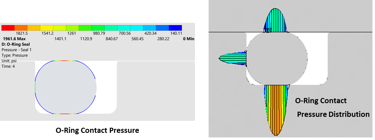
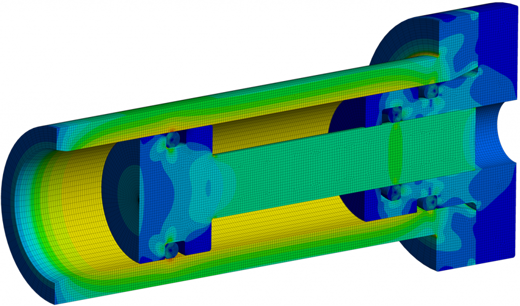
The contact pressure of O-ring # 1 (piston-cylinder seal)
Finally, here is a 3D video clip of the piston-cylinder assembly:
We can go a lot deeper with O-ring design and analysis than what is presented here. I’ve deliberately omitted details of fluid pressure penetration and how it is applied. This could be a separate blog article in the future. In the meantime, if you have questions or need help with mechanical engineering projects, please reach out to me at zaeem@endeavos.com

9 Comments
Great article! Glad to see some o-ring simulation work. Would love to see the APDL commands at some point, but the simple blog post included a lot of helpful tricks and tips, thanks!
Thanks for reading this article. I’ll certainly post the APDL commands in the near future. Also there will be a YouTube video showing how its done.
Regards,
Zaeem
Thanks for the article.
Have you posted the APDL commands somewhere? I can’t find them.
Thanks for reading. In the near future, I will revisit this article and search for the model. I’ll then post the APDL commands. It’s going to be soon.
What APDL commands have you used to implement the fluid pressure penetration?
I second Tobbie’s question
I’ll provide an explanation soon. In the process of preparing a follow-up article.
Thanks for reading.
ZK
Could I know how to determine the stress limit for the leakage? Or how can I see if there is a leakage when applying pressure to the O-ring?
Hi Tobbie,
In the process of preparing a follow-up article and a detailed Youtube Video on this topic. It will answer these questions. Please follow and subscribe to Endeavos Innovation’s youtube channel: @endeavos. I’ll be posting videos on a regular basis.
Thanks for reading.
ZK