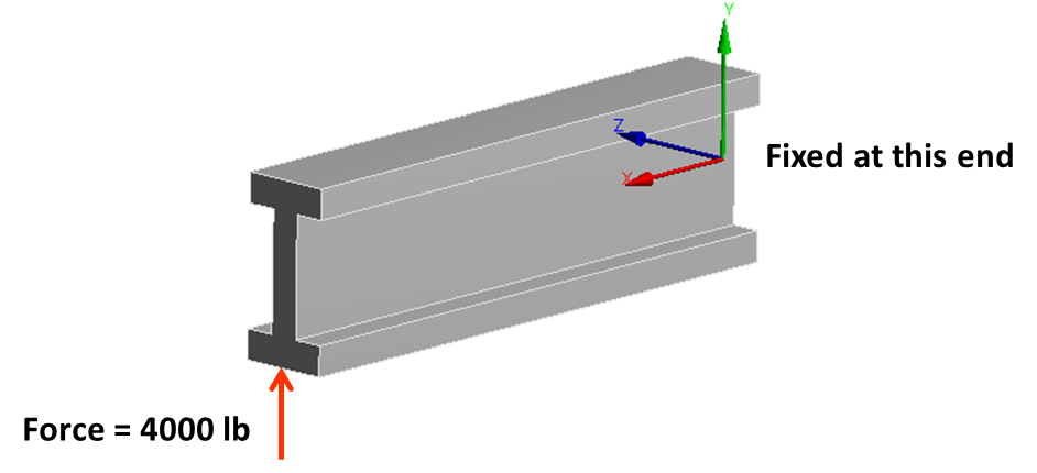
The purpose of this article is to post-process and understand FEA results by comparing with standard text book theory and hand calculations. I will use the example of a cantilever I-beam loaded by a point force at the end. Simple hand calculations based on fundamental equations of solid mechanics is the best way to validate finite element analysis. For very complicated geometry, we can at the very least validate support reactions. For the simple case of an I-beam shown below, there are two types of stress that are of interest.
- Bending stress (along X-axis)
- Shear stress (in the XY plane)

I performed a basic hand calculation to validate bending stress as shown below. The FEA result is generated using the “normal” stress option in ANSYS workbench along the X direction.
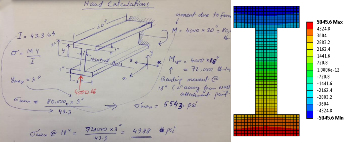
The important point to note here is that, I am comparing bending stress two inches away from the fixed end. The reason is that near the support, the stress variation is very complex and does not follow the simple beam bending stress formula. Due to Saint–Venant effect, this complex stress field dies out completely at around two inches from the wall.
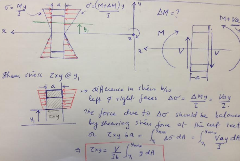
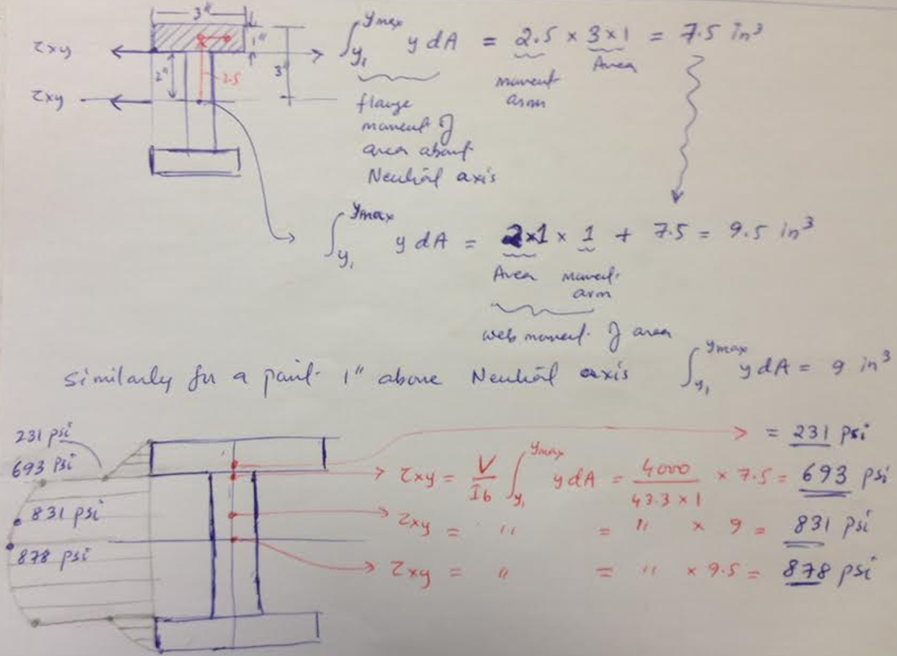
The shear stress computation is more involved. So in order to clarify the shear stress, I am presenting a simple hand derivation of shear formula below. At the fundamental level, the shear stress resists the shearing effect of the point load. The effect of shear force “V” is simply a change in bending moment between two beam cross sections separated by distance “a”. This change of bending moment causes a change in bending stress between the two cross sections which results in an imbalance force along the x-axis (beam longitudinal axis). The shear stress counters this force imbalance. The integral in the shear formula is moment of area of the cross section computed at the location where shear stress needs to be computed. For simple shapes such as an I-beam, this integral can be evaluated by inspection.
Using the shear formula, I calculated the shear stress at various locations along the middle of the beam cross section. As shown below, the shear stress is computed at the neutral axis, one inch above the neutral axis, at the interface between the web and flange (on the web side) and again on the flange side. The maximum shear stress at the neutral axis is 878 psi.
The comparison of shear stress (hand calculation with FEA) is shown below. An interesting point to note here is that the shear stress in the web near the neutral axis compares really well but as we approach the web-flange interface, our simple shear formula deviates from FEA solution. Of course, the FEA result is more closer to reality than the shear formula. Any good text book on solid mechanics will explain the limitation of shear formula in great detail. However, as a simple check on FEA, the comparison near the neutral axis is sufficient.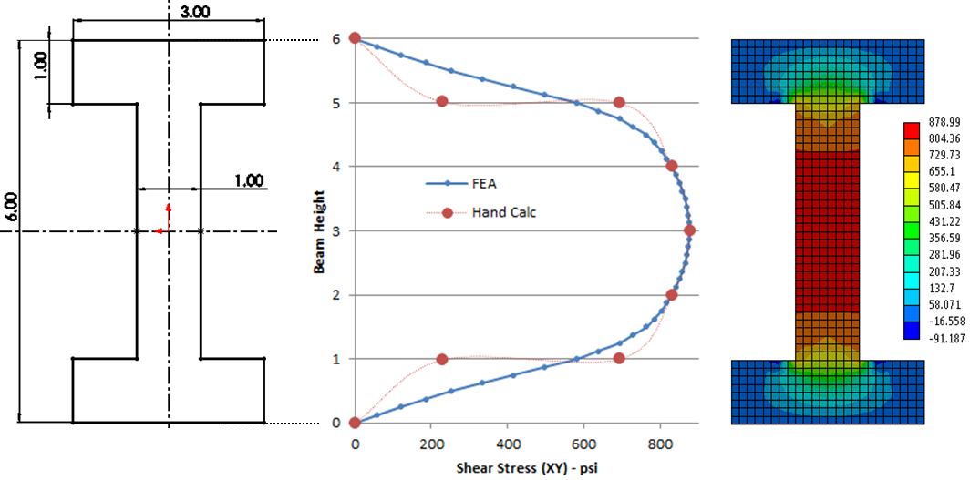
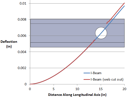
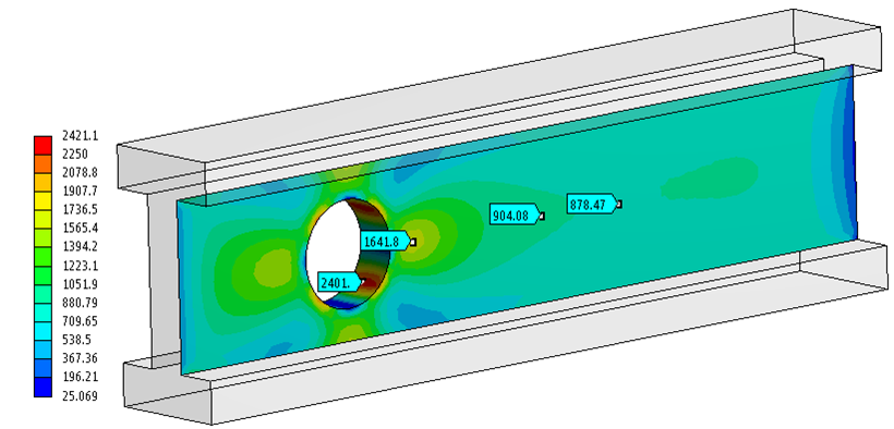
Another point to note here is the importance of shear web in resisting the shear stress. I wonder what would happen if a hole is made in the web, say for the sake of making the structure light weight. I re-ran the analysis with a 2.5” diameter hole in the web located at 15” from the wall. The shear stress distribution is really interesting. Around the edge of the hole, the shear stress peaks up to more than 2400 psi compared to maximum 878 psi for the original beam. If we move away from the hole, the shear stress returns goes back to 878 psi.
The main effect of having a web cut out is increased deflection starting from the cut-out boundary to the tip. This is fairly obvious as the web resists deflection due to shear stress. As a final check, the maximum deflection computed using text book formula for a cantilever beam with tip loading is 8.5e-3 inch. The FEA result shows 9.7e-3 inch, whereas the FEA result for beam with a web cut out is 10.05e-3 inch. The FEA results are fairly close (but more accurate) than the hand calculations. Even for the complex case of web cut out, we can use hand calculations as a sanity check.