
Motorsport is very popular in the northeastern United States with several race tracks in upstate New York alone. Endeavos Innovations was contacted by AMT Motorsport, Inc to analyze brake rotor assembly of corvette c5 and c6 models. These race cars have to be slowed down from 170 to 70 mph within a few seconds and multiple times during a lap. The brake rotor disks are typically seen glowing red hot. This puts a lot of stress on the brake rotor assembly that exceeds far above normal vehicles.
Endeavos Innovations used a finite element method involving coupled thermal-structural analysis to determine the safety of brake rotor assembly under extreme loads.
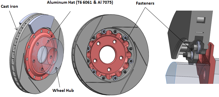
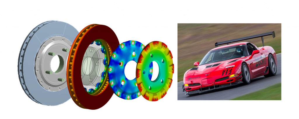
Figure 1: CAD model showing various components in the brake rotor assembly
Finite Element Model Development
The CAD model of the system is shown in Figure 1. This assembly is connected to the wheel hub on the outside and the axle on the inside. The absence of these two components can affect the analysis due to improper thermal as well as structural boundary conditions. Therefore, a simplified wheel hub and axel bodies were added to the sub-assembly shown transparent in Figure 1. This completes the model geometry used in the analysis.
The model mesh is shown in Figure 2. Mesh size was optimized in a few analysis runs in order to achieve sufficient convergence with acceptable computation time. Further computational efficiency is achieved by using hexahedral mesh wherever possible.
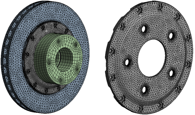
Figure 2: Finite Element Model Mesh
Loads
A lot of thought went into deciding appropriate loads. During the application of brakes, the pads are pressed on the cast iron rotor disk on either side. This creates a tremendous frictional force which also translates into torque due to the moment arm. Additionally, temperature builds up quickly as shown in Figure 3. High temperature deteriorates material strength, however, peak temperature does not coincide with peak dynamic and mechanical loads. Peak loads occur at the initiation of braking within a fraction of a second while at this time the entire assembly is at ambient temperature except rotor disk and brake pads which start to heat up quickly. A critical component is the aluminum rotor hat which largely remains at ambient temperature even after several seconds. By the time, we approach steady-state temperatures in the entire assembly, the dynamic and mechanical loads may not exist. Therefore, we may reach an incorrect conclusion regarding the safety of the system if maximum thermal and mechanical loads are applied simultaneously.
In the absence of actual physical data, it was concluded that a possible worst-case scenario is re-applying brakes after steady-state temperature distribution is reached and the assembly starts to cool down. The cool-down phase is much slower compared to the heating up phase and therefore, a steady-state temperature distribution was assumed with rotor disk maintained close to 600 F. The peak dynamic and mechanical loads were computed based on assumed uniform deceleration of the vehicle from 170 to 70 mph in about 10 seconds which amounts to a g-force of about 4.5. Mechanical loads include centrifugal acceleration due to spinning as well as pre-tension of wheel studs as shown in Figure 4.
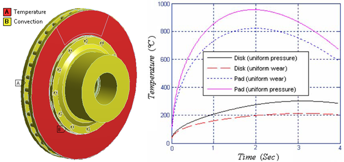
Figure 3: Build-up of temperature when brakes are applied at zero seconds. A thermal boundary condition is also shown.
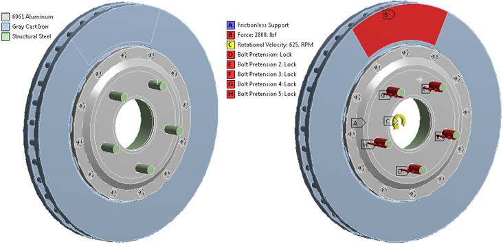
Figure 4: Mechanical loads on the brake rotor assembly

Figure 5: Temperature distribution in degree F as a result of steady-state thermal analysis.
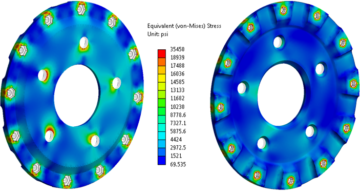
Figure 6: Von Mises stress distribution on the Aluminum hat component.
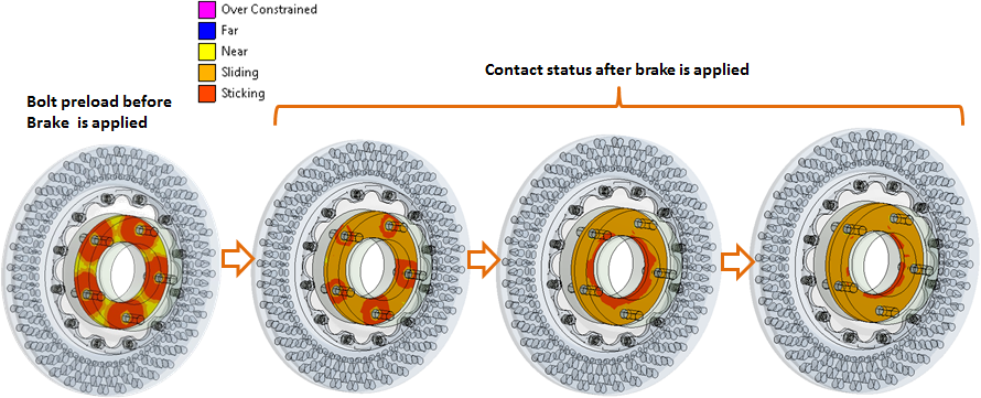
Figure 7: Contact Status of bolted (stud) connection
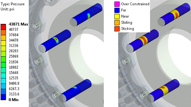
Figure 8: Contact pressure and contact status when studs come into contact with aluminum hat component at peak load.
Results and Conclusions
Steady-state thermal analysis was conducted prior to stress analysis. The contour map of temperature distribution is shown in Figure 5 for the cast iron rotor disk and aluminum hat. The stress contours are shown in Figure 6. The peak stress in the aluminum hat was found to be less than the yield stress limit of aluminum at the peak steady-state temperature.
The contact status of the bolted connection was also investigated under peak loads as shown in Figure 7 and Figure 8. At the peak loads, the aluminum hat contacting face remains to stick towards the center but slides with respect to the brake assembly around the stud-hole radius. This means studs come into contact with the stud-holes in an aluminum hat and press against it as shown in Figure 8.
Overall, the entire assembly was considered to be safe under extreme loading conditions keeping in mind the load assumptions based on which this analysis is performed. The next logical question is how long the brake assembly will last or the life of this sub-assembly under similar loading conditions. To answer this question, fatigue analysis was performed.
Overall, the client was very satisfied with the result of our analysis: