

SDM research and Engineering based in Istanbul Turkey wanted to develop two test rigs to simulate gas turbine seals in a controlled environment. SDM approached Endeavos Innovations to develop the automated test, data acquisition, and control systems for these test rigs.
Endeavos Innovations started the project with a detailed piping & instrumentation diagram as shown in Figure 1. This provides an overview of what the system entails in terms of flow, sensors, actuators, and other instrumentation and devices.
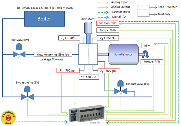
Figure 1: P & ID of SDM Test Rig
Operation Modes & Test Procedure
The test rig operation modes were discussed in detail with the client to establish the best possible operation methodology. The various operating modes are a startup, steady-state operation, transient operation, data capture, normal and emergency shutdown.
Failure Modes & Critical Warnings
A detailed failure mode effects analysis was carried out in consultation with the client to establish critical operator warnings and the best possible corrective actions. Some corrective actions were automated within the rig control software.
Hardware & Software
Endeavos Innovations selected all hardware and instrumentation based on the test rig operation and safety requirements. Some critical decisions at this phase include selection between real or non-real-time operating systems to run the test rig code. The chosen hardware for this test rig is NI cDAQ-9188. This is a modular system that can take various I/O modules as per data acquisition and controls requirements. The communication link is via Ethernet. NI Labview was chosen to develop the code.
Rig Simulator & Automatic Control Development
A rig simulator was developed based on the lumped parameter pipe flow model analogous to the electrical circuit in order to simulate the test rig operation (Figure 2). The flow characteristics of various elements such as valves were determined based on vendor specifications, whereas pipe flow resistance was computed based on standard fluid mechanics formulas.
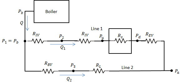
Figure 1: P & ID of SDM Test Rig
The rig simulator was used to validate the automatic control scheme for pressure control. The rig simulator was essential in providing good initial guess for PID controller gains for the real system. Rig Failure modes and corrective actions were also simulated before moving on to the real system.
Graphical User Interface (GUI)
The GUI was designed to operate both test rigs. In fact, the code was designed to be modular and expandable to enable multiple test rigs mounted on the same piping network. Endeavos Innovations has developed a library of frequently used code modules. This allows the rapid development of new code as well as simplifies and speeds up modification and upgrade of existing code.
The GUI for the two test rigs is shown in Figure 3 and Figure 4. The GUI is easy to use with uncluttered, minimal front panel controls to avoid distraction. Additionally, some controls are also dimmed and disabled automatically to guide the user to choose the right control. All the control and sensor readouts are overlaid on the test rig schematics reflecting their actual position. This type of display makes it easy to understand, speeds up learning, and prevents mistakes.
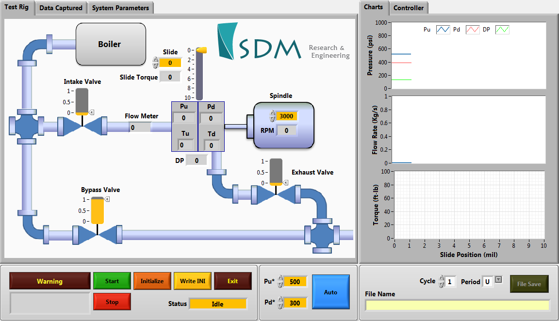
Figure 3: GUI Developed for SDM test rig
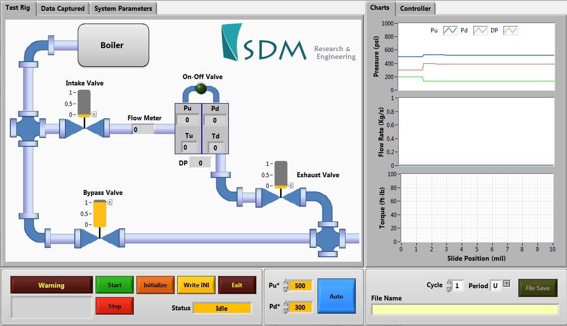
Figure 4: GUI automatically transforms for a second test rig installed on the same piping system.
Slide Motor Control
One of the test rigs consisted of a linear slide driven by ABB servo motor. Endeavos Innovations developed several custom VI utilizing active X controls to control slide motor via Labview as shown in Figure 5.
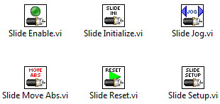
Figure 5: Custom VI developed for control of linear slide motor
Data files
The test rig data files were saved according to the client’s specifications. Here is a sample of a typical data file saved as a CSV text file that can be opened in the Microsoft Excel program.
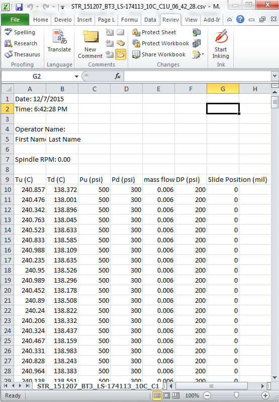
Figure 6: Same Data file
Report & User Manual
Endeavos Innovations provided a detailed operating manual for the test rig as well as an overall technical report to the client.