
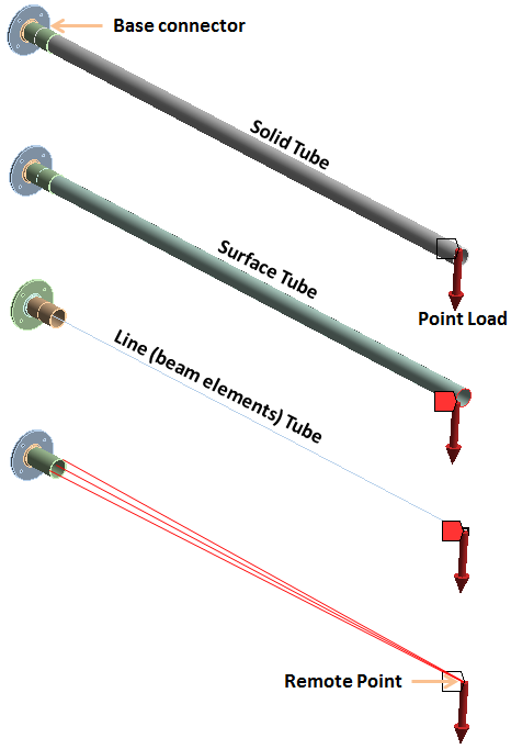
Models of various fidelity can be used for analyzing structures or any physical system. The decision is made based on desired results as well as computational resources available. In this blog, I’ll compare finite element models of varying fidelity using ANSYS finite element analysis software. The example used for comparison is a simple tubular, cantilever beam structure connected to the wall via a base connector by means of four bolts. A point load is applied at the end of the tube. For comparison, the following finite element models are used, listed in the order of decreasing fidelity and complexity:
- Solid Model
- Surface beam Model
- Beam tube
- Remote force

Four finite element models of varying fidelity were solved in order to compare results
By inspection, it is clear that the most critical part of this structure under the given load, in terms of peak stress is the tube base connector part. So the first simplification we can make is to replace the non-critical solid meshed tube by a tube having surface elements and further on by beam elements. The last model completely ignores the tube and the load is applied remotely via a remote point (RBE3) at the same location where the tube end would have been. In order to make the comparison fair, I adjusted the number of elements in solid, surface and line (beam) elements until acceptable and comparable stress convergence was achieved. In all four cases, the tube base connector mesh was kept identical since this is the critical part and the main focus of our comparison.
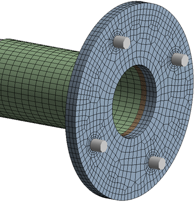
Identical solid mesh in the tube base used in all four models
Simulation results are summarized in the following table:
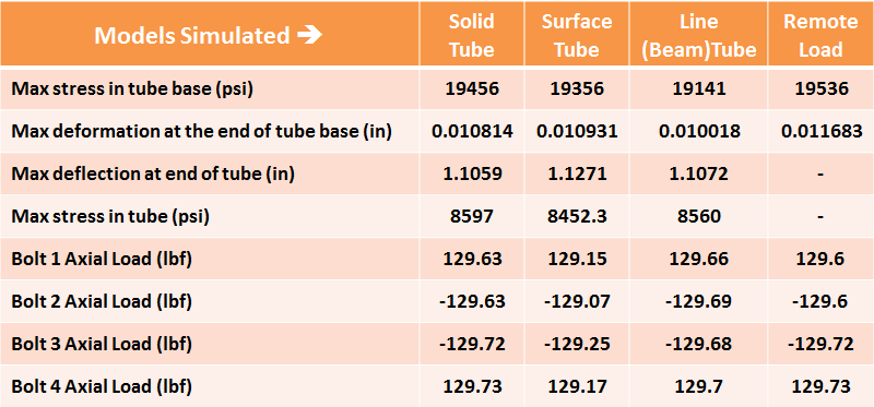
Notice that the peak stress & deformation in the tube base (our critical part) is comparable in all four cases. The max deflection of the tube (non-critical part) is also comparable except for the remote force model where the tube does not exist. Similarly the max stress in the tube is also comparable for the three models. As an additional check, the bolt axial loads also match in all cases. So as far as determination of peak stress and deformation of the critical part is concerned, all models show comparable results as can be seen in the following stress contour maps:
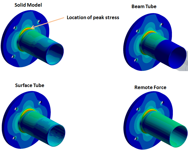
Identical stress contours in the critical structural component – tube connector
In some cases, the maximum deflection of the tube may also be critical which the remote force model cannot provide, but other than that, we basically get the same level of details in all the models. The key benefit of using the simpler FE models such as the beam and remote force is computation speed as shown in this chart:
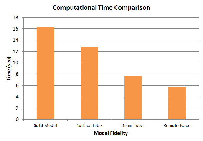
Computational time comparison. There is a significant difference in computational time between the simpler (low fidelity) models and the solid meshed model.
Even for this simple structural system, this time difference is significant. For more complicated and large scale models, a judicious replacement of non-critical structural members by a beam or remote loads can significantly enhance computational efficiency. A good example would be a large truss assembly or an airplane wing structure where the critical region of interest could be wing root attachment. In my future blog, I’ll explore this idea further to analyze a more complex truss system.